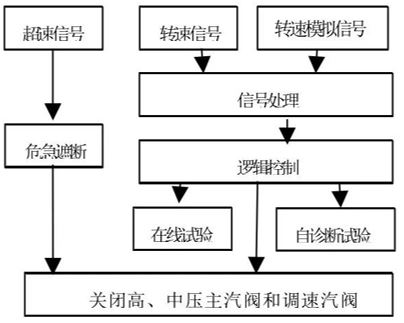
The controller collects operating parameters such as the speed of the steam turbine unit in real time. After control calculation, it outputs a valve position control signal to change the opening of the regulating valve, and ultimately controls the speed of the steam turbine unit to follow the given value.

Product architecture and features
Safety Integrity Level
SIL2/SIL3 flexible configuration hardware localization
100% domestically produced components.
The software platform is fully independent and controllable for all software and hardware technologies of the domestically produced Kylin system.
System Architecture
1oo2D/2oo3D flexible configuration
Typical Configuration
Chassis architecture: It adopts a 14-slot plug-in chassis, including 1 CU communication module, 2~3 MPU main control modules, 6~8 IO modules, and 2 PW power modules.
Module Introduction
AI module: 16-channel 4~20mA current input, double-ended input, input resistance ≤250Ω, current input.
PI module: 8 differential signal inputs, meeting the RS422 level specifications in GB/T11014-1989 "Electrical characteristics of balanced voltage digital interface circuits".
DI module: 16-channel dry contact signal input, response time <10ms, query voltage 24V.
AO module: 8-way 4~20mA current output, load resistance>600Ω.
DO module: 8 relay contacts, contact voltage allowable range: 5~30VDC; contact capacity: 2A, resistive load.
CU communication module: 2 Ethernet interfaces, 2 RS485 interfaces: The Ethernet interface is used to communicate with the host computer. The RS485 interface is used to communicate with other devices through RS485RTU and ASCII protocols to transmit process data. Both communication interfaces support hot swapping.